Normal Maps issue with AMD GPU (invisible in 3D view)

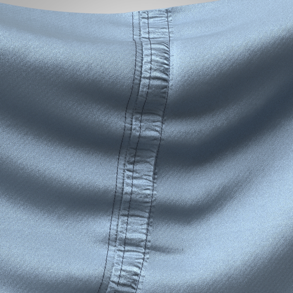
Hello! I need help with normal map and GPU settings for CLO 6.1. Recently I tested this software on my notebook with built-in old-generation GPU (AMD 6620G+AMD Radeon HD 6470M). At texturing stage I noticed some problems with normal maps for all graphics (Graphics, puckerings, topstitches). First of all, puckerings are not shown in 3D window at all, even with Show Puckering button turned on (increasing intensity gives nothing). Topstitches (type Texture) shown as flat color texture only, even when I add a normal map for every stitch texture. As for Graphics (like embroidery), I use color PNG texture and Normal Map, generated by PixPlant. Color is OK, but normal map doesn't affect 3D view and moreover, in UV Editor I see it tiled within the graphic image border, although I set tiling as None in Normal Map settings. In UV Editor I see all these elements (puckering, stitches, graphics) baked onto the general Normal Map of the garment, and this map exports very well. But when I decided to test such normal maps in DAZ 3D Studio for quick render, I found they have no (or barely visible) effect for rendering, for other rendering software I cannot say for sure. The same flat image as in CLO itself:
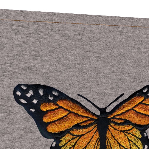
What may be the reason of these problems? Wrong settings for normal maps of my GPU is incapable to render such maps in CLO3D properly? I use such settings in User Preferences - VBOs are turned off (to prevent crashes), Antialiasing = 8 or 16 at texturing stage. All normal maps for graphics are 90-100% intensity, in PNG. All buttons (Show puckering, topstitches etc) are turned on.
The full baked Normal Map, where I see the tiling within the butterfly graphics -

Maybe, wrong format for Normal maps (OpenGl or DirectX, tangent space or world space etc)? In Pix Plant 3, I cannot set them for sure, so which software I should use to generate proper maps for CLO (in Photoshop this option doesn't work for me)? What is the format for CLO baked maps?
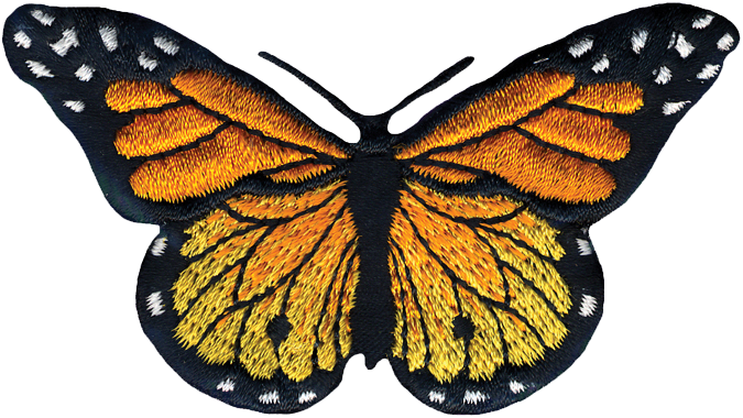
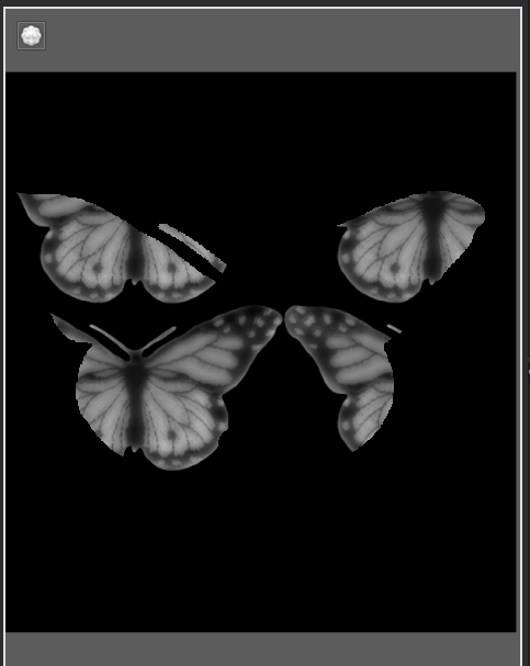
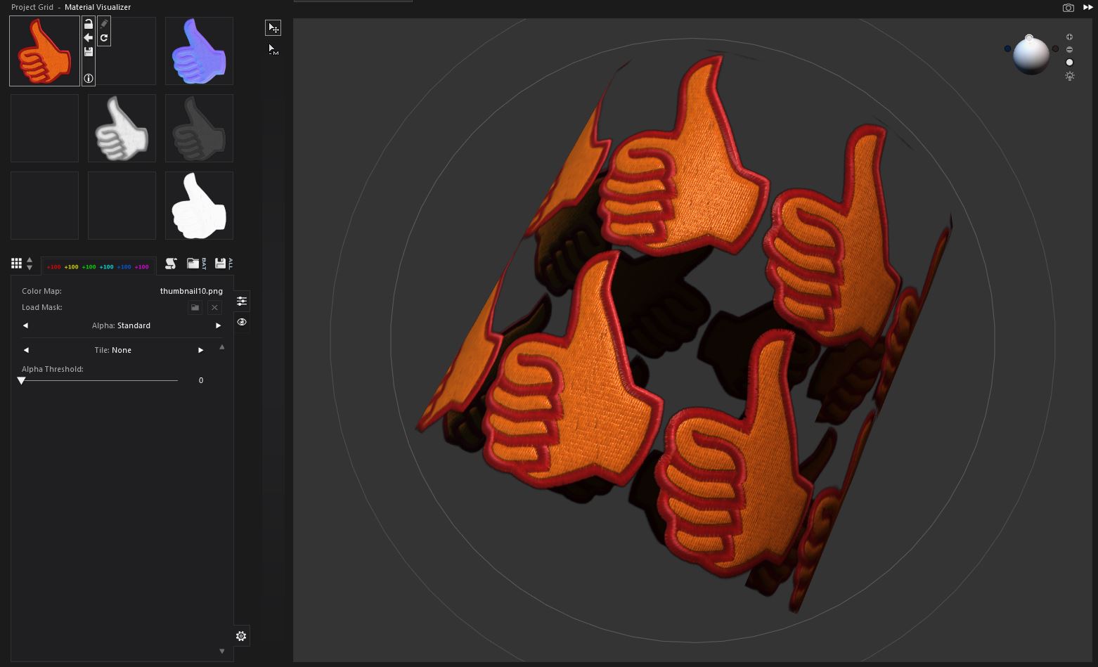
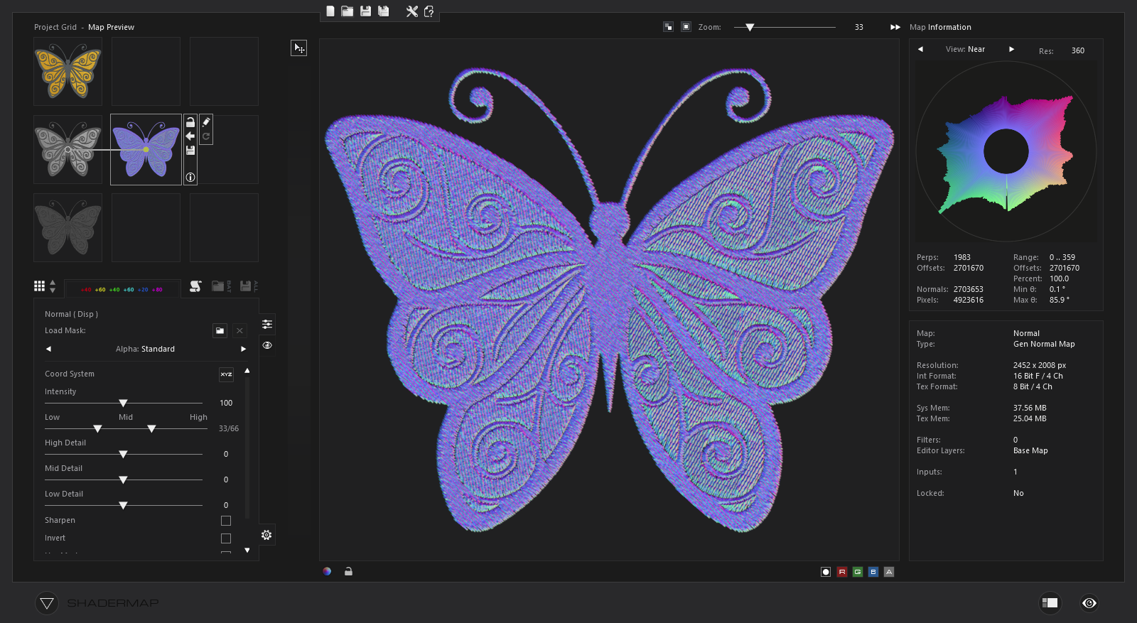
As an example, 2 maps for this butterfly embroidery I tried to use in CLO3D recently - I upload them without any editing:
Color diffuse:
Normal map from Pix Plant (I convert it from desaturated color image):

-
Hi ilifan2021,
If you cannot see the puckering result in 3D window, you may first check the setting of 3D Trims Display > Show Puckering is turning on / off. If you turn it off, you won't see any puckering on your 3D garment.
If you think the puckering result or the graphic's normal map is not strong enough, you can try to increase its Intensity in the Property editor.
To make your embroidery graphic being more "3D", you can try to add normal map + displacement map at the same time.
For more details, please refer to https://support.clo3d.com/hc/en-us/articles/360025439933-Displacement-Map-ver5-1-0-
0 -
Thanks, ottoline, but I think my issue slightly differs - I found many ways to imitate embroidery even in Photoshop, but the question is how make these elements to be shown within CLO3D in 3D view. So far I found that CLO6 understands only Normal maps in JPG, not PNG, and moreover, it can auto-generate normal maps. It seems that auto-generated maps work best within CLO, and I found I can export them as surface textures. I'm not sure but when I bake the general Normal map combined from these auto-generated maps, it works better in other 3D software (like DAZ) and I can even see the effect of puckering through the diffuse texture while rendering (puckerings are normal map only). So I think CLO uses some specific format for normal maps, but which namely? I see you use Shader Map, not Pix Plant - can this software make suitable maps for CLO? As for Displacement,Opacity and Roughness\metallic Maps - should I make them also in JPG only, never Png again?
Also I found that puckerings can have their own diffuse texture, but CLO provides no example, so I wonder how to make such custom texture for a denim realistic seam, for instance. It seems, I must prepare a rectangular color image in Photoshop to make it seamless, and then load it into CLO as diffuse and make an auto-generated Normal map, right? How to save this map for later use? (CLO exports Fabric and graphic surfaces only). Same for custom stitches, beadings etc. By the way, I tried to export various sizes of baked maps and found that common fabric texture looks well even in 1024, but small details like stitches went out blurry even in PNG over 8000 px. Is there a way to make them sharper, especially within the smaller maps, not more than 4096 px? Should I increase Anti-aliasing or remake stitches maps to make them contrast etc? My final goal is to make final baked general maps for garments and use them as usual clothing textures both outside and within CLO instead of heap of fabrics, topstitches etc.
And the main question is - why I don't see the effect of normal maps in 3D Window? I turned on all necessary buttons - 3D Trims Display > Show Puckering, Show Topstitches etc. Maybe I must turn on VBOs - what is their purpose? I keep this option off to speed up simulation and prevent sudden crashes. I suspect my GPU is a bit old for complex graphic calculations, but it works well for rendering in other software and (usually) can recognize any normal maps for 3D models. What are necessary 3D settings for CLO to work flawlessly?
UPD^ - I discovered another issue with maps - when I import my own maps to Normal and Displacement fields, they will always be tiled instead of applying to texture. Looks like this -

The same for imported normal maps. Only auto-generated maps work well. Tiling is set to None!
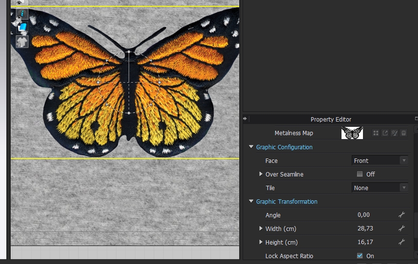
What I do wrong? Why custom maps tile within the graphic image and only diffuse texture works without issues?
0 -
Your Ref: > Can this software make suitable maps for CLO ? Yes > shader map is maybe slightly better than pixplant (there is a free version you can try out) as it has a node graph type layout (grid) and more adjustment for filter type effects like in photoshop, so it is more versatile in that respect. It also has normal and depth map painting on layers.
You can use .png but try RGB .png and not RGBA.png format.
The embroidery normal maps are a function of the light, they should be as diffuse as possible without highlights. best to run a depth map using the grey scale of the artwork and then blur it with graduated tone. Then blend that with a normal output of the stitch.
Puckering > yes you can blend these and get pretty much any type of pucker map into the system you want. See this post for help on that >> Link
Your Ref:> why I don't see the effect of normal maps in 3D Window? > Because the 3D window view is not the same as the vray render engine view ( including path tracing, photon mapping). This means when you render with 'vray' render engine inside CLO3D you are getting the vray material shader and any texture maps or settings you set up for that in fabric stack. And when you use the 3D window WIP (work-in-progress) PBR view you are simply looking at a simpler render view from the CLO3D internal WIP render engine.
Your ref: What are necessary 3D settings for CLO to work flawlessly? > See recommended hardware >> link
In terms of the 3D settings CLO3d default settings and standard fabrics from the library should get you going okay, flawlessly is not really a mode that any software operates in as that is dependent on the project requirements and the end users knowledge. The only answer I could possibly give is - training and manual reading, which should help you set everything the way you want for any project. The rest is learnt which is a 'flawless' approach. :-)
 0
0 -
Your Ref:> why I don't see the effect of normal maps in 3D Window? > Because the 3D window view is not the same as the vray render engine view ( including path tracing, photon mapping). This means when you render with 'vray' render engine inside CLO3D you are getting the vray material shader and any texture maps or settings you set up for that in fabric stack. And when you use the 3D window WIP (work-in-progress) PBR view you are simply looking at a simpler render view from the CLO3D internal WIP render engine.
OK, it seems I got it - then, 3D window render should not display normals and displacement at all, these maps are purposed only for rendering via Render menu? Thanks for explanation, I havent't seen this info anywhere else. But I struggle now with the tiling problem mentioned above. All my custom normal maps work well with Trims (topstitches, puckers), which are naturally tiling, but I cannot switch off auto-tiling for a single Graphic image. Have you ever stumbled upon such issues in CLO? I attempted to import maps via Texture Editor, all the same. The only thought which comes to me - maybe, the tiling within borders of a graphic image follows the tiling of main fabric texture? Should I make a separate pattern for graphics instead of straight applying onto fabric surface? I found a couple of lessons, which recommend this way for all embroideries, badges etc, aside from flat color prints. How do you make such things in CLO?
(Of course, there is a way to add such badges in Photoshop, editing all maps in a single PSD file, but I hoped that new CLO offers a quicker way of simultaneous baking all map elements. )
0 -
Your Ref: OK, it seems I got it - then, 3D window render should not display normals and displacement at all ...
No > the normal map will show up in the WIP (Work-in-progress) 3D window preview BUT vray's render engine displacement is specific to that engines material >shader< use. However normal maps will show up on fabrics in the WIP 3D preview window > that is detailed in the manual. >> Displacement map manual link
Video link about CLO3D maps
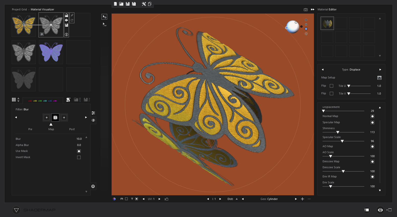
CLO3D can create a normal map from a diffuse 'desaturated' image however that is generally used for doing various colorways, for embroidery you may want to create a bespoke normal map from a greyscale albedo image (no high lights) and then match that to a color albedo for the artwork to make a diffuse image. That is what I do in shader maps node graph for instance. (see below)
See this video for embroidery as a pattern piece.>> Video link
Your Ref: > I cannot switch off auto-tiling for a single Graphic image.
Correct - When creating a fabric (material shader) you are creating a tile map texture. In that instance it is a fabric repeat. In the video above you will see how they deal with that by aligning a scale tile repeat with a edge bleed (eg: 2mm) to logotype pattern outlines and then stitch that to the hat. Similarly for any 'fabric' shader you setup you would need to use CLO3D's fabric texture ATLAS UV map as the single image to that project object (garment assembly) as defined in CLO3D's UV workspace (top right tab in CLO3D). CLO3D can save the entire project and patterns out as a set of UDIM texture map atlas. This means you can texture that component or scale your texture map outputs (eg: shader map) to that UV scale pattern piece as a image for normal displacement etc.
See video about baking UV maps >> Video link
So that is 2 approaches.
0 -
Similarly for any 'fabric' shader you setup you would need to use CLO3D's fabric texture ATLAS UV map as the single image to that project object (garment assembly) as defined in CLO3D's UV workspace (top right tab in CLO3D). CLO3D can save the entire project and patterns out as a set of UDIM texture map atlas. This means you can texture that component or scale your texture map outputs (eg: shader map) to that UV scale pattern piece as a image for normal displacement etc.
Thanks, ottoline, it was very helpful. This approach with a separate pattern solves the question of customizing textures - it's easier to have a simple square sewn on the fabric and change its own texture image in Photoshop, than retexturing all the clothing. Though many software is accustomed for collapsed (stacked) UV tiles within 0-1 limits, ot for UDIM. Is there any handy converters for uV to convert from UDIM to usual stacked UV tiles?
0
Comments