Looking for a workflow to export pattern pieces for laser cutting

Hello, I am pleased to have access to a large format (1500 mm x 1200 mm) laser cutter and I want to use it to cut my pattern pieces.
I have come close to finding a great workflow but it doesn't check all the boxes I need.
What I am currently doing is creating seam allowances for my pieces and then exporting to PDF with mm @ 100% scale and ONLY Pattern Outline and Seam Allowances selected.
When I load the PDF into Lightburn (my laser cutting software) I see both the pattern outlines (which are undesired but required in CLO3D in order to export) and the seam allowances. Thankfully Lightburn shows these as separate layers and I can turn off the pattern outline layer.
All of this is fantastic! However, exporting to PDF does not automatically layout the pieces for optimum use of my fabric and I have to guess how to lay them out in my 2D arrangement. This is a time killer and screws up my 2D <-> 3D workflow.
What I really wish is that the Print Layout mode supported Export to PDF at 100% scale. This seems like it would be a complete workflow.
Can anyone suggest a way to refine my described workflow to meet my needs and optimize my material usage without lots of manual guesswork?
Thanks in advance!
Braveness23
-
When I laser cut I use the plot file (PLT) which is a format specifically geared to plotter type movements as it's a graphical format, that is all you generally need for passing to any cutting/CNC cutter, and when you export you have the option to determine what you want as the cut line within your software and also what you export from CLO3D. Looks like your software takes in the PLT format so you should use the plot export from CLO3D. File > Export > Plot.
Any good CNC should read plot files which is the industry standard for vector based driven plotters which are basically the same as pen driven plotters > then all you need to do on your CNC software is determine the laser cut path based on that software.
You will need to input your print/plotter/CNC bed layout size for the print file from the > print mode before you run the plot file, and you may want to separate pattern pieces on the plot by their fabric shader. The plot file is based on the cut for each fabric type. So if you want all patterns to appear on a single plot cutter sheet you would need to apply all patterns with the same fabric shader in the fabric stack. Otherwise to break all the patterns up into their fabric cutter plots you would use the fabric type to run a cut/plot for that group of patterns that will be nested or laid out according to that print sheet.
If you have graded patterns that you want to plot as a nested layout you can also do that from the print workspace tab (top right).

All CNC plots would normally be run from plot/cutter files as they are geared to vector exchange and the numerical code that is used between plotters. This is typical of running production cutter sheets for sample making. if you are also running digital printing onto the fabric prior to CNC cutting you need to maybe state that as a workflow as it's slightly different based on what digital print machine you have ie: roll based output or flat bed.

When you save you will have a plotter file. Then you can generally import that to your CNC software to layout or run the cutter (CNC) according to the layers and features you want to cut.

When you load your plot file then your next software would typically take that plot file format in and you would process that according to your CNC needs (eg: making a plot file into a cutter layout with any additional machine paths - nesting, laser paths ID marks etc) relative to that CNC's software. So this is when and where you decide to select the cut line for the CNC cutter path > in your next software from the PLOT file you exported from CLO3D.
Failing that > you might use the DXF-AAMA format to send the vector CAD data pattern to your next pattern CAD software that works with your cutter nesting software > that is also a typical approach when the 2D external pattern CAD and CNC nesting for making cutters are within the same software system driving the sample cutting hardware.
However using a pdf export off CAD patterns for running a CNC cutter sheet for sampling would be highly unusual as that may introduce additional data errors and layer structure issues unrelated to simple vector CAD data and the conventional HPGL (Hewlett Packard Graphics Language) Plotter file standard that most people use for this task.
Note: if you use DXF on your laser cutter as an alternative format to exchange data between CAD systems you need to appreciate that DXF (Engineering CAD) is slightly different to the fashion DXF-AAM/DXF-ASTM standard - layers and ref: blocks. So you would need to check that out with your laser software to see how accurate and complete the pattern shape line work comes in if you opt for that type of output and data exchange. So for that reason the CLO3D plot file exchange should be much better as a choice.
0 -
Wow! I am so grateful for such a terrific and complete technical explanation from someone who clearly has done this before! I understood most of what you said and can certainly follow up on my own to fill in what I didn't understand or just don't have experience with. I am indebted to you!
0 -
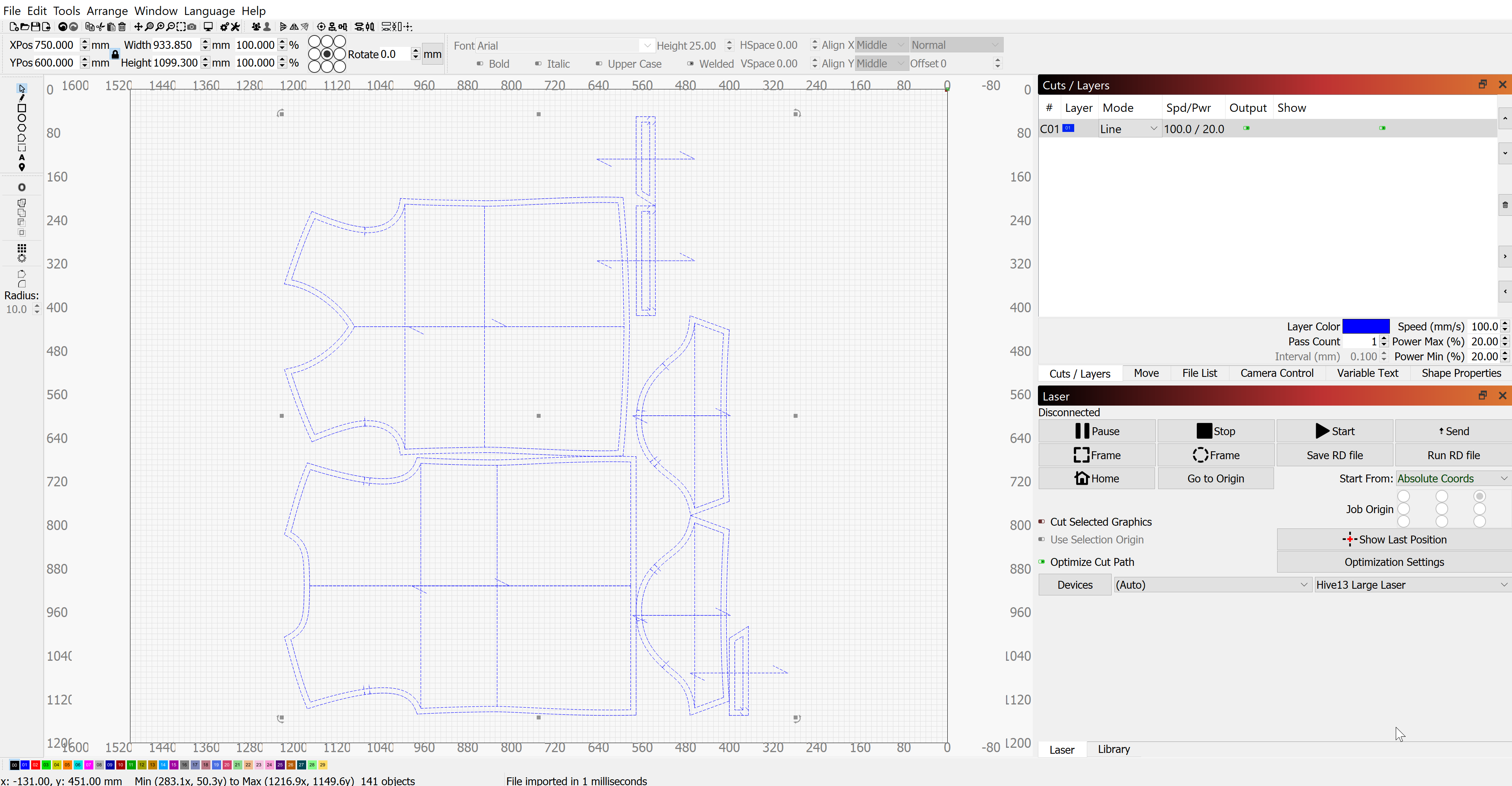
I think I followed along with what you said but when I import the PLT file into Lightburn it all shows up as a monolithic layer. Obviously if I burn this it will include all manner of cuts that will leave my material in tatters. This solution solves my problem of minimizing my waste of material but does not give me the option of selecting which lines to actually cut. Seems like a deficiency in my CNC software but I'm green enough to not know. Can you advise?
 0
0 -
Yes it's often relative to what your laser cutter is generally used for, if it's a CNC cutter used within a fashion pattern cutting and nesting software there is generally the process tools to handle size nesting and layout for your production from DXF-AAMA/DXF-ASTM or plot files - so that is maybe a step and function you are missing as this looks like a general laser cutting software. It does export as a single layer so you need to maybe change how you export elements - you can usually ungroup (explode) a single nested plot group of patterns.
NOTES:
With most plot files (see >> link ) they have layers, line-weights etc associated with their outputs, which may mean you could look at the layering and lines types within your software and create a template that recognizes the CLO3D plot file elements better, as it does look like you have a cut/layer table. But if it can not do that you may need to do it manually and reduce what pattern piece elements you export out. Then you could isolate just 3 pattern elements, cut line, notches, and pattern line.
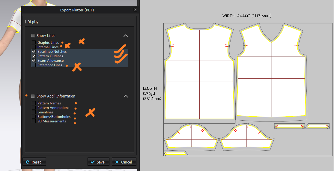
Just export the line layers that you want in your plot file from CLO3D, (Show Lines: Toggle List) as you can export only what you want when you export by switching off items in the toggle list, eg: you could ignore the internal lines, and pattern line and just export the cut line. And maybe export 3 plot files one for each layer, then bring them together in your laser software's layer mode, where you assign a new line-type,layer, and color for that plot you import. Usually when you import a plot file you can select the line types,colors,layers and re-assign them using a template that you save for re-use. That way you do it once and when you next import the plot file it sorts it all into the right colors,layers and line types into your layer stack.

You can export less information in the plot file (the minimum is the cut-line and the pattern line) but now the important notches are missing as the only export option is > baseline/notches, so to get around that problem of being able to separate them see what I do below with changing baselines to internal lines which means you only now have notches and no baselines on the patterns. (A work-around)

Or the pattern line and cut line with notches and base line. You can maybe switch the baselines to internal lines in CLO3D so you can switch those off.


Switch off what you don't need in the plot file so it's reasonably clean.
(Below) after the baseline and internal lines are deleted You could just delete the baselines if you wanted and switch the internal lines off.

So now it is nice and clean as a plot file : With only the cut line, notches, and pattern line. Then just assign these in your software to separate layers.

Hope that helps.
0
Comentários