Problem with the creation of 3d Logos in CLO3d

Hi! I've recently started to use clo3d in order to create concepts of soccer jerseys. I'm struggling with the creation of 3D logos that are made of TPU, a particular plastic. I've checked a tutorial on your website and also got explained how to do it, but there are some problems which I hope can be easily resolved.
So, from what I've been told, I need the crest image, a bump map which I created in Photoshop and a Normal map (they didn't use it, but as I tested it helps to create a realistic effect). The bump map should be used as Displacement Map, but when I do it (amount 3 - particle distance - 4), I get this "wobble effect":
After looking at the tutorial on displacement maps, I noticed that at Particle Distance 1 the example looked better, but if I try the same with the crest it looks like this:
The only way I managed to decrease this effect is with Amount 1 and Partical Distance 10, but at the same time the bump effect isn't as evident and realistic as I would like (and if you look closely, you can see that it's still present in some parts):
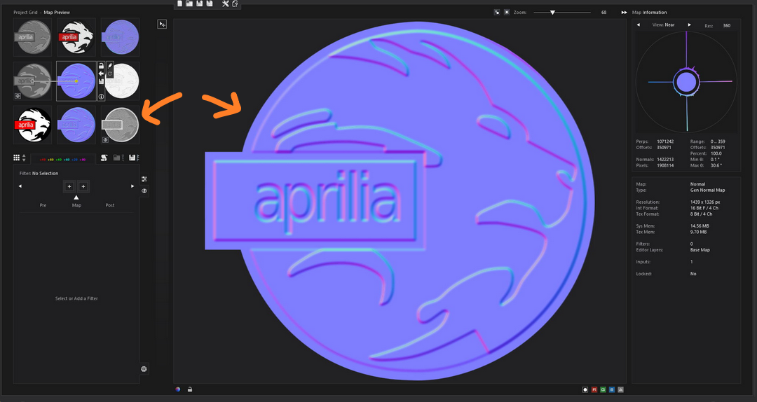
As you can see below, these are the images I used for displacement maps: I used a bump map, a displacement map like the one in the tutorial and a normal map, but they all give me the same problem. 
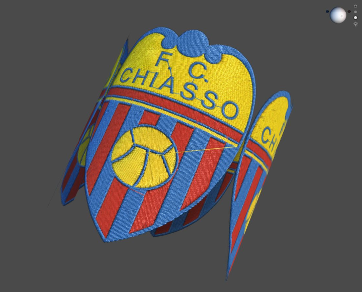
And the effect I'm trying to reproduce is this (all created by other designers with clo3d):
Can someone tell me what am I doing wrong? Can it be a problem regarding the version of it? (mine is 5.1)
Thanks in advanced.
-
Alessio, every map has its purpose (as you might know so far). And using grayscale gives you an large amount of possibilities for getting what you need. From what you wrote I can sense you will be better off if you were to understand very clearly how the displacement works and how the maps do what they do. For instance, your displacement maps has very little grading in the edges (blurriness) that means that your patch will jump out of the 0 level ground (the t-shirt) directly into space. That is why it looks floating. I will suggest you learn more about it in a video that helped me understand it at the beginning. Then you can work with some other Vray tutorials on displacement and apply it here in CLO. This is a good starters video:
https://www.youtube.com/watch?v=XtkZCEpOu2k
0 -
Take your color vector (diffuse image layer) and make it into a grey scale map for the height.
Break the artwork down into height fill areas and then apply the shade of grey for the topography of the badge at the level you want in the final simulation. (see below in workflow and texture node graph)
Pick level of grey to represent the height (0 > 126 > 255)
See how the artwork below off the vector work get used as a basic grey scale fill (you have that missing in your image files) the grey scale color represents the height in my badges final simulation (height map) and the blurring of that image (gausian blur 3-5 pixels) gives me a soft rolled transition for the edges according to my needs for each area.
The normal map is also created from the height map to give me the world light angles for the surface changes to improve the final simulation.
You can apply what ever top texture you want (eg: embroidery or etched texture ) into the simulation using a separate texture map based on blending the two texture fills off the artwork.
Below see how two normal maps (blend) combine to produce the final light angle off the surface (micro surface detail) and how the depth (height) map is the simple grey displacement map used to generate the 1st smooth normal (macro height of the molded badge profile).
This simple arrangement off 2D vector artwork gives you all the maps you need to use in CLO3D to give the molded badge (macro) height, and (micro) surface texture detail.

 0
0
Comentários